4 Bit Multiplier Block Diagram
Multiplier array ripple rca unsigned multipliers cascade Multiplier array 4 bit multiplier circuit diagram
Figure 1 from DESIGN OF MODIFIED 32 BIT BOOTH MULTIPLIER FOR HIGH SPEED
Multiplier bit vedic verilog code vhdl diagram block vlsi using 4x4 implementation 2x2 multipliers adders coding nanoelectronics Multiplier schematics Multiplier array circuit multiplication logic applications
Multiplier bit circuit binary
Multiplier array unsigned reconfigurable multipliersMultiplier array unsigned Block diagram of the multiplier: two 8-bit operands a and b areFour bit multiplier design..
Solved write the verilog module to describe the 4 x 34 bit multiplier circuit diagram Multiplier operands multipliedBlock diagram of 8-bit multiplier using 4-bit carry pre-computation.

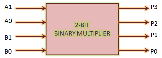
Binary multiplier
Bit multiplier adder vhdl wroteWallace multiplier 4x4 A 4×4 bit ripple carry array multiplier (rca) [12], [16].Figure 1 from design of modified 32 bit booth multiplier for high speed.
Booth multiplier modified speed circuitsMultiplier computation 4: block diagram of an unsigned 8-bit array multiplier.Alu bit diagram multiplier block mini introduction figure final.
![A 4×4 bit ripple carry array multiplier (RCA) [12], [16]. | Download](https://i2.wp.com/www.researchgate.net/profile/Maaruf-Ali/publication/333968081/figure/fig3/AS:772998130847744@1561308524131/A-44-bit-basic-Braun-multiplier-12-16_Q640.jpg)
Multiplier bit adder vhdl code based am stuck but
4-bit binary multiplier circuit2 bit multiplier using logic gates : vlsi n eda Block diagram of an unsigned 8-bit array multiplier.Multiplier design2.
Vhdl 4-bit multiplier based on 4-bit adder4 bit multiplier circuit diagram Binary multiplier bit diagram block logic using two gates figure numbersBlock diagram of binary multiplier.

Block diagram of array multiplier for 4 bit numbers
Design of compact baugh-wooley multiplier using reversible logic4-bit multiplier design2 The block diagram of 4-bit vedic multiplier4 bit multiplier circuit diagram.
A 4×4 bit array multiplier [12], [16].Baugh multiplier wooley wooly reversible logic Traditional 4 bit array multiplier.Multiplier bit binary using multiplication adders schematic calculator divider digital 4x4 adder logic gates electricaltechnology electronics possible electronic multipliers types.

Multiplier binary
Multiplier verilog adders39: block diagram of the 4x4 wallace tree multiplier. Multiplier array.
.


